Bridge demolition Dubai
Engineered as one staged operation
Bridge demolition services in Dubai require detailed planning for span removal, lifting operations, temporary works, and traffic protection measures. Stone Beam delivers engineered demolition solutions for road, pedestrian, utility, and infrastructure bridges across Dubai and the UAE, with every activity sequenced before mobilisation to ensure safe execution rather than improvised during closure operations.
Spans · lifting · traffic control























Overview
Not a larger version of building demolition
The structure may be prestressed, post-tensioned, continuous across several supports, or dependent on bearings and bracing designed for one specific load path.
It may cross a live road, rail corridor, waterway, or public area. It can also pass through temporary conditions during removal that were never part of its original permanent design. For these reasons, bridge removal is planned as a staged engineering operation, with an understanding of the structural system, current condition, tendon arrangement, bearing restraints, lifting weights, access, crane positions, traffic windows, and the required final condition.
Stone Beam develops project-specific bridge demolition scopes for Dubai and the UAE, coordinating the physical package with the appointed consultant, asset owner, traffic team, utility owners and lifting specialists where their approval is required.
Request a technical review
Send the bridge location, owner or asset authority, available drawings, inspection reports, span arrangement, structural material, route or asset below, proposed closure windows and required final condition.
Request a demolition quote
Use this form layout on the live page to qualify leads before a call.
Bridge removal" isn't every foundation by default
Removing a deck is a very different cost and programme from removing the same bridge down to the pile cut-off level and reinstating the corridor below.
Work element
Superstructure
Bearings & restraints
Substructure
Foundations
Approaches & retaining works
Utilities
Traffic / possession
Reinstatement
Six risks concentrated in one work area
Temporary behaviour, prestress, live assets below, heavy irregular components, restricted closures, and public consequences, all at once.
Stable in permanent condition, vulnerable after a deck strip, diaphragm, or bearing restraint is removed, each stage needs an understood load path.
Project-specific review of tendon arrangement, anchorage, and continuity, never assumed to behave like ordinary reinforced concrete.
For roads, rail corridors, waterways, public routes, and live services, the method protects the asset and includes a recovery strategy.
Large weights, difficult centres of gravity, and nominal crane capacity aren't enough; check the actual radius and ground conditions.
The engineering sequence fits the authorised window and never relies on an assumption that the route stays closed until finished.
Uncontrolled debris, slurry, or disruption affects users beyond the boundary and is coordinated across structural, lifting, and traffic disciplines.
The method follows how it was built
Six structural systems, six sets of removal constraints.
Solid, voided, or beam-supported slabs, continuity, hidden voids, and reinforcement arrangement drive the cutting or lifting plan.
Diaphragms, composite deck action, bearing details, and tendon arrangement all affect girder-by-girder dismantling.
Bonded/unbonded tendons, anchorages, deviators, and pier-table behaviour: visual inspection alone can't define a safe cutting sequence.
Cross-bracing, gusset plates, and connection continuity control stability during crane-assisted dismantling.
Whole-span lift is possible where weight, centre of gravity, and release sequence are verified; otherwise, sectional dismantling.
Structural work begins only after the owner confirms isolation, drainage, and safe removal of carried services.
No universal method, a real project combines several
A whole-span lift should never be selected for marketing effect, only where the engineering and logistics support it.
Method
Whole-span lift-out
Sectional saw-and-lift
Girder-by-girder dismantling
Steel bridge dismantling
Mechanical demolition
Robotic / restricted-zone work
A crane is selected from the lift, not a tonnage label
A "250-tonne crane" can have very different available capacity at different radii; the nominal class never replaces the load-chart check.
Lifted weight
Centre of gravity
Crane radius & configuration
Trial & contingency
Lifting points & rigging
6. Span removal
Approved cutting, lifting and dismantling with hold points.
7. Substructure removal
Piers and foundations removed to agreed limits.
8. Waste & transport
Segregated and processed through the approved route.
9. Reinstatement & handover
Cleaning, survey, records and authority inspection completed.
1. Scope
& interface
Elements to remove/retain, asset owner, waste and handover confirmed.
2. Records
& investigation
Drawings, inspection reports and geometry verified.
3. Engineering
& method
Removal sequence, temporary works, crane plan and prestress strategy developed.
4. Approvals
---
Demolition permit, traffic management, possession and insurance coordinated.
5. Enabling
works
Isolation, access, temporary support and monitoring baseline set.
Nine stages, scope to handover
The visible demolition may occur in one short window; the engineering and approvals behind it take much longer.
No universal price per square metre
Driven by the structure, possession, lifting, and interface requirements, not the deck area alone.
Structural factors
Cutting & removal
Crane & lifting
Traffic & possession
Environmental & waste
Final handover
Not a fixed rate
Drawings, inspection reports, span arrangement, closure assumptions, and required final condition are needed for a reliable proposal; unknown structural or access conditions should never be hidden inside a fixed rate.
Coordination, scope clarity, verified resources
Not unsupported claims of owning every specialist capability, engineering before equipment.
Method selected after the bridge system, condition, asset below and closure window are understood.
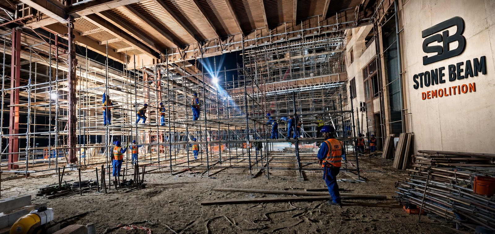
Cutting, lifting, steel dismantling, controlled demolition and monitoring within one sequence.
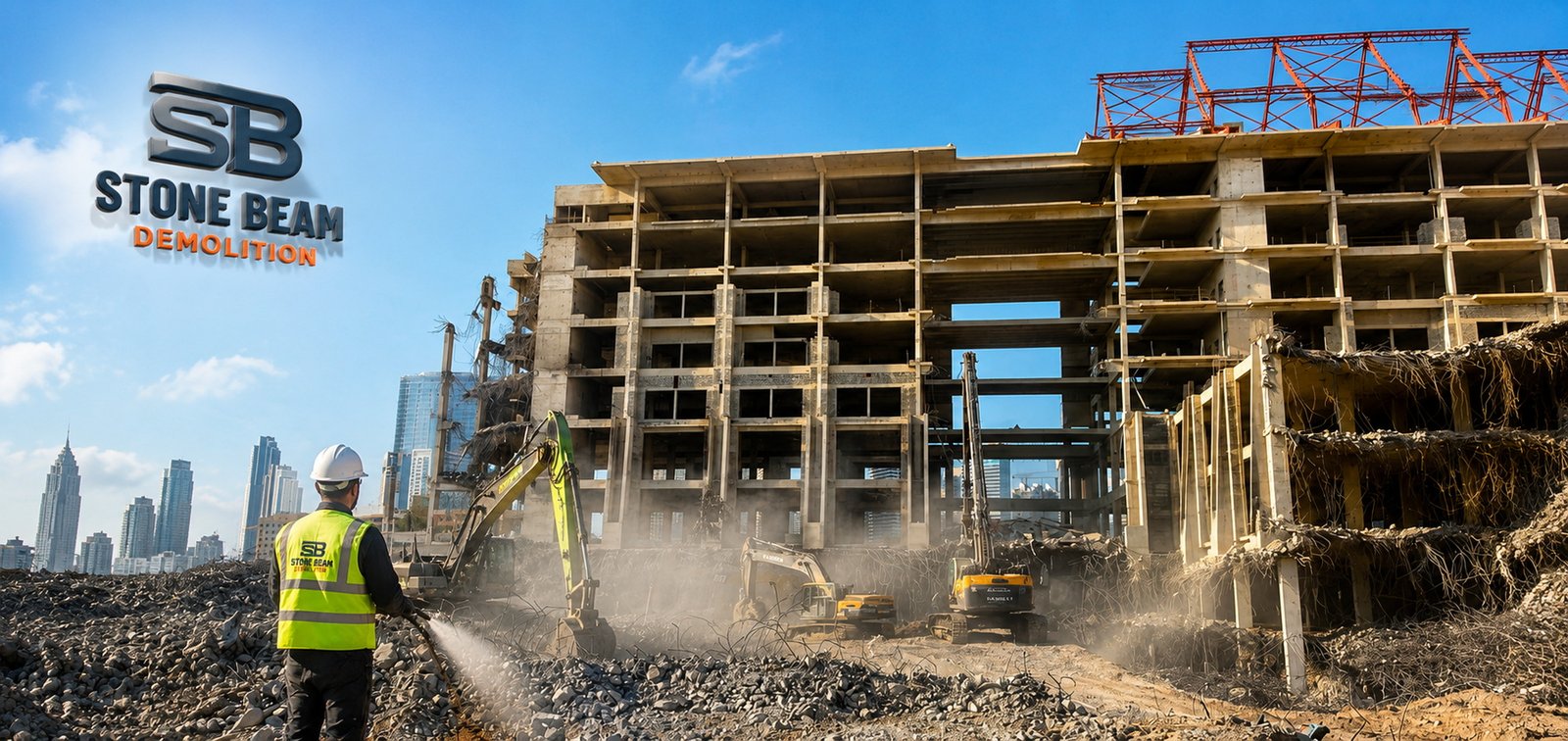
Superstructure/substructure limits, crane responsibility, traffic and utilities named in the proposal.
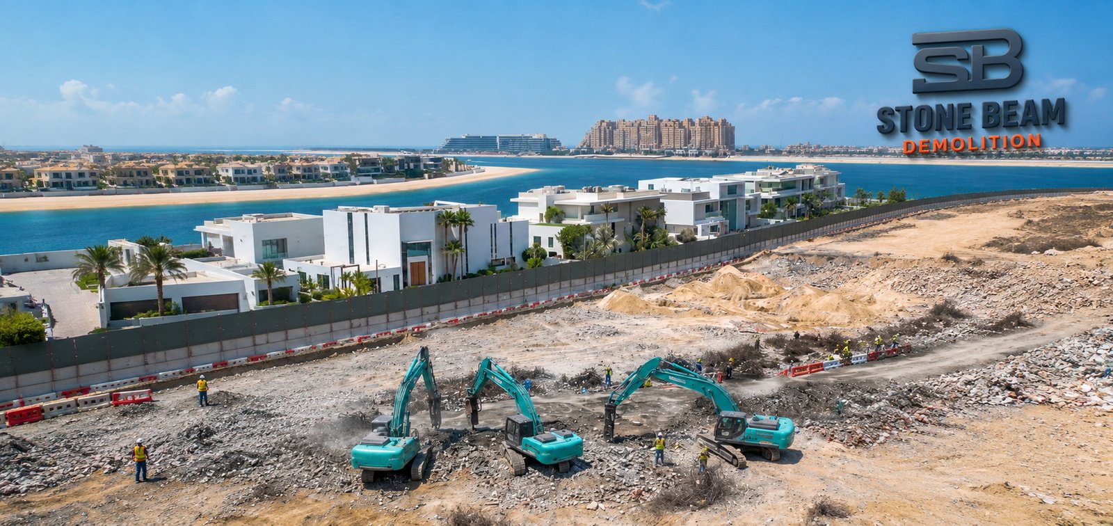
Named-project or rail-adjacent claims published only with project records and client permission.
Common questions, answered straight
What road authorities, consultants and contractors ask before they call.
Engineered removal or dismantling of a bridge, span, deck, girder or pier through a staged sequence controlling temporary stability, lifting, traffic, utilities and the asset below
No. Cranes are common for controlled removal, but some projects use mechanical demolition, dismantling, robotic equipment or other specialist methods depending on site conditions.
From the verified lifted weight, centre of gravity, actual radius, boom configuration, rigging, wind, ground capacity and the manufacturer's load chart — never a generic crane-tonnage label.
Possibly, where the complete weight, structural integrity, lifting points, release sequence and laydown area are all verified — otherwise sectional dismantling may be safer.
The project first reviews tendon arrangement, continuity, diaphragms and bearings, then girders are released and lifted in a designed sequence with temporary restraint where required.
No. It has a different impact profile from breaking, but still produces equipment forces, noise, cooling water and slurry — and the section must be supported before final release.
Only where staged structural analysis, traffic separation, barriers and authority approval demonstrate the retained part can safely carry temporary and operational loads.
Not the normal method for dense urban or live-infrastructure projects — where considered, it requires specialist studies, additional NOCs and extensive exclusion planning.
Full closure, traffic diversion, controlled lift-out, temporary platforms, barriers and screens — temporary protection is designed for the actual expected loads.
Still have questions?
