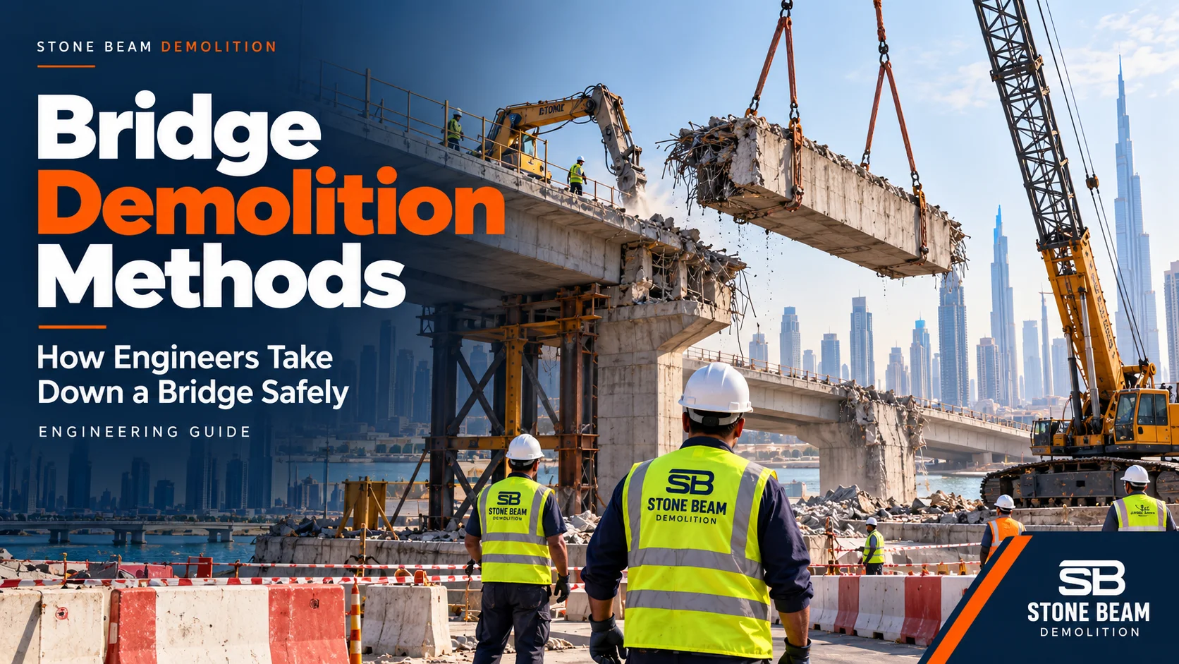
Bridge demolition is the planned removal of all or part of a bridge while the structure remains stable at every intermediate stage and the road, railway, or water below stays protected. Engineers choose from five main bridge demolition method families:
- Mechanical demolition with excavators, crushers and breakers
- Saw-cut and lift, also called sectional removal
- Girder-by-girder dismantling
- Whole-span removal by crane or SPMT
- Span-by-span removal using a movable scaffolding system, gantry or reverse erection
Supporting techniques such as hydrodemolition and remote-controlled robots work within these families, and explosive demolition is a specialist international option. The right combination depends on the structural system, what lies below the bridge, and how long the corridor can be closed.
This guide explains how each method works, an illustrative removal sequence, what changes on post-tensioned bridges, how a lift is checked, and which approvals apply in Dubai. If you have a live bridge scope in the UAE, see Stone Beam’s bridge demolition services in Dubai.
Engineering note: this is a guide to methods and principles. Every real bridge needs a project-specific engineered demolition plan, checked and accepted by the responsible engineers and the asset owner before work starts.
By Eng. Awad Ashour, Founder & CEO, Stone Beam Demolition
What does bridge demolition involve?
A bridge demolition scope falls into one of three types, and the type changes the engineering more than most clients expect.
- Full removal: deck, girders, bearings, pier caps, piers, abutments and foundations down to an agreed level. “Full” still needs a stated foundation depth and handover condition.
- Partial removal: part of the structure is retained, for example a deck replacement on existing piers, parapet and edge-beam removal for widening, or removing a footbridge superstructure while keeping its foundations. Partial jobs can be harder than full ones, because the retained structure must stay undamaged and stable.
- Phased removal: the bridge is removed in stages around traffic possessions or adjacent works, so each stage leaves a structure that must stand on its own until the next window.
Partial removal is not a niche case. Caltrans’ Bridge Removal Manual, Chapter 3, states that partial removal is the most common type of bridge removal on its projects. It ranges from concrete barrier rail removal to removing lacing from steel truss bridges, and is often incidental to rehabilitation and widening. Before comparing quotations, mark the removal limits on the drawings and state whether surfacing, parapets, services, bearings, piers, pile caps, debris transport and reinstatement are included. Two quotes labelled “bridge demolition” can otherwise price very different jobs.
Why is demolishing a bridge harder than demolishing a building?
Bridges and buildings both need engineered demolition, but a bridge raises four particular challenges:
- The structure changes as you remove it. A continuous deck, a girder with its bracing, or a box with its tendons is designed to work as a whole. Remove one part and the forces in the rest are redistributed, sometimes into members that were never designed to carry them. A span that was safe in service can become unstable halfway through demolition.
- Something important is underneath. A bridge usually crosses a live road, a railway, a creek or a utility corridor. Falling debris is not acceptable, so the method is often chosen by what happens below rather than what is efficient on top.
- Machines load the deck differently from traffic. A 30-tonne excavator or a crane outrigger on a partly cut slab is a concentrated load on a structure that no longer spreads load the way it was designed to.
- Prestressed bridges store energy. Pre-tensioned and post-tensioned members hold large locked-in forces. Cutting them without understanding the tendon system can release that energy suddenly.
This is why professional guidance such as the ASCE Manual of Practice No. 157, Bridge Demolition Engineering: Best Practices, treats bridge demolition as an engineering design problem. It has its own loads, temporary states and checks, and is not only a machinery task.
An illustrative bridge demolition sequence
For a simply supported beam-and-deck bridge, removal often runs broadly in the reverse order of construction, from the lightest non-structural items down to the foundations. Treat the order below as an illustration of the logic, not as a default method for every bridge:
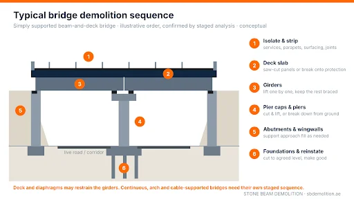
Figure 1. Illustrative removal order for a simply supported beam-and-deck bridge (conceptual, not a design).
- Isolate and strip: divert or disconnect services carried on the bridge, then remove lighting, signs, barriers, parapets, surfacing, and expansion-joint hardware. This reduces dead load and exposes the structure for survey.
- Remove the deck slab: by saw-cutting into liftable panels or by mechanical breaking onto a protected surface, depending on what is below.
- Remove the girders: one by one with cranes, keeping the remaining girders restrained against lateral buckling, or together with the deck if the span is lifted out whole.
- Remove pier caps and piers: once the superstructure is gone, piers are no longer restrained at the top. They are cut and lifted in sections or broken down from the ground, with the exclusion zone in place.
- Remove abutments and wingwalls: usually late in the sequence because they often retain approach embankments, which need temporary support or regrading.
- Foundations and reinstatement: pile caps and piles are removed or cut down to the agreed level, then the ground, road or channel is reinstated.
Two cautions apply. First, the deck slab and diaphragms often provide the lateral restraint that keeps the girders stable, so removing them before a substitute restraint is in place can create an unstable state. Second, on continuous, cantilever, arch, and cable-supported bridges, removing the deck first can overload what remains. Caltrans’ manual requires the remaining structure to be checked for stability at each stage of a complete removal, particularly when equipment works from the deck. In every case, the order is confirmed by a staged structural analysis rather than by habit.
How each bridge demolition method works
The five method families below are often combined on one project. A footbridge might be saw-cut at its bearings, lifted out whole and then broken down mechanically on the ground.
1. Mechanical demolition
How it works: excavators, often long-reach machines, fitted with hydraulic crushers (pulverisers), shears and breakers bite the concrete down into rubble. The machines work from the ground, from an abutment end or, after engineering checks, from the deck itself. Reinforcement is cut out and separated as the concrete is crushed, and the debris falls onto a protected surface such as a protection deck or a rubble mat over the closed road. Controlled demolition techniques keep the retained structure undamaged where only part of the bridge is removed.
Often suited to: reinforced-concrete bridges over corridors that can be closed, piers, abutments and wingwalls, and spans already lifted out to the ground. Main limitations: debris, dust, noise and vibration; it needs a closure below or a protection system designed for the debris; and machine weight on the deck must be checked at every stage.
2. Saw-cut and lift (sectional removal)
How it works: the deck is cut into panels or blocks with diamond wire saws, wall saws and core drills. Piece size is developed together with the crane set-up, the piece’s own capacity when lifted and the stability of what remains, so that each gross weight stays within the crane’s rated capacity at the working radius. Lifting points are then provided, for example, lifting anchors installed in cored holes or slings passed through them, in a rigging arrangement designed and checked for that piece. Before the final release cut, the crane takes up the designed load. The piece is held by the rigging and any temporary supports, so that it does not drop or swing when the cut is completed. The release sequence is part of the lift plan. The piece is then lowered to the ground or onto a trailer and broken down away from the corridor.
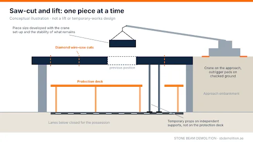
Figure 2. Saw-cut and lift concept: cut, support, take up the load, release and lower one segment at a time. Conceptual illustration, not a lift or temporary-works design.
Often suited to: bridges over live roads, railways or sensitive assets where debris must be kept off the corridor, and possessions are short. Main limitations: each cut changes how the remaining deck is supported, so cut-free pieces may need temporary props. Cutting slurry must be captured, and the crane, its outrigger pads, and the ground beneath them are checked for every lift. Our concrete cutting services cover the wall sawing and coring that support this method.
3. Girder-by-girder dismantling
How it works: the deck slab, or the in-situ stitch between precast girders, is removed first. Before diaphragms and cross-bracing are cut, the stability of the girders left standing is verified and substitute restraint, such as temporary bracing, is installed where the analysis needs it. Each girder is then lifted off its bearings by one crane or by two cranes in tandem. Steel girders are unbolted or flame-cut at planned points; precast concrete girders are often lifted whole. On steel bridges, hot or cold cutting is decided at the planning stage. Hot cutting needs hot-work controls and a fire watch, and old coatings are tested first because they may contain lead or other hazardous materials that change the cutting and disposal method.
Often suited to: simply supported precast concrete and steel girder bridges. Main limitations: once the deck and bracing are gone, individual girders, especially the last ones, can be laterally unstable, so the removal order and temporary restraint are designed together. Tandem lifts need a specific lift plan.
4. Whole-span removal by crane or SPMT
How it works: the span is freed at its bearings or expansion joints and removed as one unit. Large cranes lift it out, or self-propelled modular transporters (SPMTs) drive under it, jack it off its supports, and carry it to a breaking area off the corridor. The US Federal Highway Administration’s manual on using SPMTs to remove and replace bridges says they are mainly considered where closure time must be minimal and an off-site staging area with a feasible route is available. Its example comparison of traffic impact lists 2–3 days per span for conventional demolition against 25–30 minutes per span for an SPMT move. Those are durations of disruption to traffic in an illustrative US comparison, not the length of a demolition project, which still includes the off-line preparation.
Often suited to: corridors where closure time is the main constraint and there is access for heavy cranes or SPMTs plus a receiving area. Main limitations: very large equipment, ground-bearing and transport-route checks, and continuous spans may first need to be cut into units that can be supported and moved safely.
5. Span-by-span removal: MSS, gantries and reverse erection
How it works: on long multi-span viaducts, a movable scaffolding system (MSS) or launching gantry supports each span while it is dismantled, then moves to the next span. It is the same kind of equipment used to build segmental viaducts. For segmental, cantilever, or incrementally launched bridges, engineers may also study reverse erection: removing segments using a concept based on how the bridge was built, sometimes with strand jacks to lower heavy units. The original erection records, and any strengthening since, decide whether reverse erection is feasible.
Often suited to: long viaducts where ground access below is poor, or closures must be limited. Main limitations: high set-up cost, specialist temporary-works design and long planning periods, so it generally pays back only on large structures.
Supporting techniques
Hydrodemolition uses high-pressure water jets to remove concrete down to a set depth while leaving reinforcement intact. It is used for deck rehabilitation, joint replacement, and widening, where part of the deck stays in service, and the run-off water needs collection and treatment. It is a partial-removal technique, not a way to demolish a whole bridge.
Remote-controlled demolition robots with breakers or crushers work inside box girders and in confined areas where an operator should not stand. They also suit decks that need a lighter machine, once the deck has been checked for the robot’s own load. They complement the main method families rather than replacing them.
What about explosive demolition?
Explosives are used internationally on some large bridges, usually over water or remote corridors, often with pre-cutting so that members fail at planned points. Caltrans’ contract specifications prohibit demolition by explosives and by free-falling masses (wrecking balls) on its projects. In dense urban corridors, licensing, exclusion zones, debris and adjacent assets make them seldom practical, and any proposal for a UAE bridge would need the competent authorities’ determination. This guide therefore focuses on the mechanical and lifting methods.
Bridge demolition methods compared
| Method | Often suited to | Main limitation | Typical effect on the corridor below |
|---|---|---|---|
| Mechanical demolition | RC bridges, piers and abutments over closable corridors | Debris, dust, noise, vibration; machine load on the deck | Closure, or a protection deck designed for the debris |
| Saw-cut and lift | Bridges over live roads or rail; short possessions | Temporary support of cut pieces; crane and ground checks | Short, repeated closures under the lift zone |
| Girder-by-girder | Simply supported precast or steel girder bridges | Lateral stability of remaining girders; tandem lifts | Closure under each girder lift |
| Whole-span (crane or SPMT) | Corridors where closure time must be minimal | Very heavy equipment, ground bearing, receiving area | One closure per span move; long preparation off-line |
| Span-by-span (MSS, gantry, reverse erection) | Long multi-span viaducts | High set-up cost; specialist temporary works; long planning | Reduced closures below, depending on the scheme |
| Hydrodemolition (supporting) | Deck rehabilitation and widening | Partial removal only; water treatment | Lane-by-lane working |
| Robots (supporting) | Confined areas, box interiors, weak decks | Low output; complements other methods | Depends on the main method |
| Explosives (specialist) | Large spans over water or remote corridors | Licensing, exclusion zones, debris control | Large exclusion zone for a short period |
Comparing methods for a real bridge? Send the drawings and closure constraints, and our engineers will review the method options with you. Request a technical review.
How engineers choose the method
No single question decides the method, and every path ends with engineering verification. In practice, five questions narrow the options quickly:
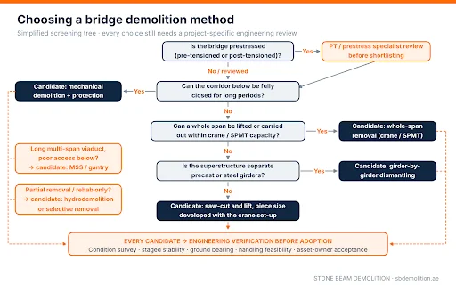
Figure 3. Simplified screening tree: it identifies candidate methods; it does not select or approve one.
- Is the bridge prestressed? If yes, a specialist review of the tendon system comes before any method is shortlisted.
- Can the corridor below be closed, and for how long? Longer closures open up mechanical demolition. Short night or weekend windows push towards saw-cut and lift or whole-span removal.
- Can a whole span be lifted or carried out within available crane or SPMT capacity and site access? If yes, whole-span removal can give the shortest closure over the corridor, as the FHWA traffic-impact comparison above shows.
- Is the superstructure made of separate girders? Precast and steel girder bridges often suit girder-by-girder dismantling, provided lateral stability is controlled.
- What size of piece can be handled at the working radius? This sets the cut pattern for saw-cut and lift, and it is where crane capacity, ground conditions and closure length meet.
The shortlisted method is then verified against the bridge’s actual condition, its temporary stability at each stage, ground bearing, handling feasibility and the asset owner’s requirements.
How Stone Beam supports bridge demolition planning
We plan bridge and elevated-structure demolition around traffic, utility and authority interfaces. Our planning typically includes a site visit, an assessment of the structure, a services review, the method statement and risk assessment, engineered sequencing, monitoring where required, controlled debris removal and handover. The project consultant receives our method statement and risk assessment for the approval process before work starts.
On the cutting side, we scan slabs and walls before cutting or coring and issue marked-up findings for engineering review. We use diamond wire sawing to remove thick reinforced-concrete sections in controlled pieces where the approved scope calls for it, and we cut and core PT slab openings under the structural engineer’s and PT specialist’s release. See our bridge demolition services for how we scope a project.
Bridge types in the UAE and what each demands
The UAE’s road network includes many concrete flyovers, interchange ramps and pedestrian bridges, a number of them prestressed. Widening and interchange upgrades also generate partial-removal scopes, such as deck replacement, ramp realignment and footbridge replacement.
| Bridge type | Method families often evaluated | Decision-changing concern |
|---|---|---|
| Precast girder flyover or ramp | Girder-by-girder after deck removal; whole-span if within capacity | Stitch and diaphragm removal; stability of the last girders |
| Post-tensioned box girder (continuous) | Staged saw-cut and lift; span-by-span on long viaducts | Continuity over piers and tendon condition (see the PT section) |
| Reinforced-concrete slab bridge or culvert | Mechanical, or saw-cut and lift over live traffic | Stability of retained slab and supports in partial jobs |
| Steel footbridge | Whole-span lift or sectional dismantling | Lateral restraint once connections are cut |
| Concrete footbridge over a main road | Whole-span lift, or saw-cut into a few segments | Crane capacity at radius and closure length |
| Creek or channel crossing | Sectional removal with marine plant | Debris recovery, silt control and navigation |
| Bridge over an operating railway | Sectional or whole-span lift in rail possessions | Possession length and operator access rules |
Load paths and temporary stability: where bridge demolitions go wrong
The load path is the route that loads take through the structure to the ground. Demolition changes it at every stage, and the critical moments are often intermediate states rather than the start or the end. Engineers check these situations in particular:
- Unbalanced removal on continuous spans: removing deck weight from one side of a pier while the other side is still loaded creates an out-of-balance moment at the pier. It can lift the far end off its bearing. Removal is therefore planned symmetrically, or the imbalance is checked and resisted.
- New cantilevers: cutting a continuous deck can leave a length of deck cantilevering past a support it used to span onto. The hogging moment over that support may be far larger than anything the original design checked.
- Girders without bracing: a girder that was stable as part of a braced deck can buckle sideways once its diaphragms and slab are removed, especially under wind.
- Equipment on a weakened deck: an excavator or crane is placed where the analysis shows the deck can carry it, often over main girders or webs rather than on a cut slab panel. Its load is checked for the deck as it exists at that stage.
- Bearings and restraints: a lifted or partly cut span can slide off bearings that were not designed for the new movements; temporary restraints may be needed.
The practical tools are a staged structural analysis that models each demolition step, and temporary props and bracing where the analysis needs them. They also include hold points: defined stages where work stops until the engineer confirms the structure is behaving as predicted, often with movement monitoring.
Post-tensioned bridge demolition: what changes
In a post-tensioned (PT) bridge, steel tendons run through ducts in the concrete and are stressed after casting, then locked off at anchorages. In continuous girders, the tendons usually follow a draped profile, low near midspan and high over the piers, where continuity tendons tie adjacent spans together. In segmental box girders, some tendons may run outside the concrete inside the box, deviated at diaphragms. Actual layouts vary with each design.
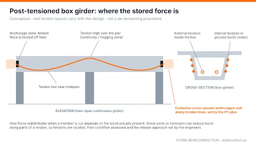
Figure 4. Post-tensioned box girder: draped tendon profile, anchorage zones and continuity over the pier. Conceptual; real tendon layouts vary with the design.
Three questions decide how a PT bridge is approached:
- How well are the tendons bonded? In a bonded (grouted) system, the tendon is tied to the concrete along its length; in an unbonded system, the force is held mainly at the anchorages. Real tendons can sit between the two: grout voids or corrosion may reduce bond over parts of the length. How much force is released, and where, when a member is cut depends on the bond actually present, the tendon type and the structural system. That is why grout condition is investigated rather than assumed from drawings; fib Bulletin 110 on managing post-tensioned bridges explains why duct and grout defects are often invisible from outside.
- Where exactly are the tendons? Cuts are located from as-built tendon drawings and confirmed by investigation. Concrete scanning helps locate ducts near the surface, but it may not detect deeper tendons and does not prove the condition of a tendon or the force in it.
- How will the force be dealt with? The structural engineer and PT specialist decide how tendon force is managed before any cutting, including the order of work and the exclusion zones around anchorages and along tendon lines, for the specific bridge.
The core review steps are shared across PT bridges, although the details differ with each system: identify the tendons, assess their condition, analyse the structure, then obtain specialist approval before any cutting. The PT review is treated as a separate engineering hold point. The same principles apply to PT slabs in buildings, covered in our post-tensioned slab demolition guide.
How a lift is checked: a worked example
For saw-cut and lift, piece size and crane set-up are developed together, alongside the piece’s own capacity when lifted and the stability of the bridge left behind. This illustrative example shows the logic of the weight check. It is not a lift design or a crane selection, and the numbers are not from a real project. A real lift plan uses measured dimensions, the actual density, and the specific crane’s load chart and configuration.
| Step | Illustrative value |
|---|---|
| Deck panel size | 10.0 m × 3.0 m × 0.25 m thick |
| Concrete volume | 10.0 × 3.0 × 0.25 = 7.5 m³ |
| Panel weight, using about 2.5 t/m³ for reinforced concrete | 7.5 × 2.5 = 18.75 t |
| Add rigging and lifting accessories counted against the chart (spreader, slings, shackles, and the hook block where the chart requires it), assumed | + 1.0 t → 19.75 t |
| Add an allowance for surfacing residue and weight uncertainty, here 10% (an assumption for this example, not a general allowance) | 19.75 × 1.10 ≈ 21.7 t gross load |
| Working radius: measured horizontally from the crane’s centre of rotation to the load’s centre of gravity, taking the largest value anywhere along the lift path | Say 22 m |
| The check | The rated capacity at the maximum radius, in the actual boom, counterweight and outrigger configuration, must exceed 21.7 t with the margin required by the project’s lift policy |
The weight check is only the start. A lift plan for a bridge segment must also cover:
| Lift plan item | Why it matters |
|---|---|
| Lifting point design | Anchors, cored holes and slings must carry the load with the sling angles actually used |
| Section capacity when lifted | A panel spanning between lifting points can crack or fail if it was never designed to be lifted that way |
| Centre of gravity and rigging geometry | An off-centre load tilts, swings and changes the radius during the lift |
| Ground or structure under the crane | Outrigger or track loads need checked ground, often off the bridge deck |
| Wind and dynamic effects | Large flat panels catch wind; lifting and slewing add dynamic load |
| Release sequence and temporary supports | The piece must stay supported until the crane holds it and the final cut is made |
| Exclusion zone and communication | Nobody under the load; one person directing the lift |
If any check fails, the team revisits the options: a different crane position or set-up, other lifting equipment, or a different cut pattern. A smaller piece is not an automatic fix, because new cuts change support conditions and stability, so any change goes back through the structural and lift reviews. Many lift procedures treat a lift above a set share of rated capacity as a critical lift that needs a more detailed plan. In US steel erection rules, for example, OSHA 29 CFR 1926.751 defines a critical lift as one exceeding 75% of the crane’s rated capacity or needing more than one crane. On a UAE bridge, the threshold follows the standard and lift policy adopted for the project.
Working above live roads, railways and water
Live roads
Over a road, the method is shaped by the closure that the traffic authority can approve. Many road-crossing removals are planned for night or weekend closures, with a protection deck under the work zone, an exclusion zone around each lift, and barriers separating live lanes from the work area. In Dubai, the RTA Traffic Diversion Drawing Technical Checklist asks for diversion drawings that show the protected work area, lane cross-sections, closure times, and signage. It calls for concrete barriers with end terminals on closures longer than 8 hours, and truck-mounted crash cushions rated TL3 on roads of 80 km/h and above. Traffic analysis with counts is required for closures longer than 24 hours on arterials, expressways and freeways, and sometimes for shorter daytime closures.
Night work is not automatic. The conditions of RTA’s Major Roads Diversion Permit prohibit noise-causing activities at night in residential areas and on major roads passing through them. The restricted hours are 9 pm to 7 am on weekdays, and 10 pm to 10 am on Saturdays and Sundays. Near housing, noisy steps such as hydraulic braking have to fit the permitted hours, and the work plan is agreed with the authorities before the closure is booked.
Railways
Over an operating railway, work happens only inside possessions granted by the rail operator, under its access rules. Possession length often decides between whole-span and sectional removal, and the overhead line and track below need their own protection.
Creeks, channels and the sea
Over water, the concerns are debris recovery, silt curtains to contain fines, navigation notices, marine plant such as barge-mounted cranes, and the stability of that plant while lifting.
Monitoring, dust and waste
A monitoring plan states what is measured, where, and with which triggers. Typical measures are structure movement in mm and ground vibration as peak particle velocity in mm/s at nearby assets, plus noise and dust. It also names who reviews readings and who can stop work. Debris is segregated into concrete, steel, and other streams. Concrete and reinforcement are usually recyclable, but recovery rates should come from weighbridge records rather than assumptions. In Dubai, waste transport follows Dubai Municipality’s Technical Guideline No. 2 on waste collection and transport.
Which approvals apply to bridge demolition in Dubai?
There is no single “bridge demolition permit”. The approval route starts with who owns the bridge, whether a roads authority, a master developer, a railway operator, or a private owner, and where it sits. Works in the Road Right-of-Way in Dubai are governed by Executive Council Resolution No. (54) of 2021, Regulating Works in the Right-of-Way.
| Approval or record | What it covers | What it does not cover |
|---|---|---|
| Asset-owner consent and technical acceptance | Permission to alter or remove that bridge, and acceptance of the method | Road-network or utility permissions |
| RTA Construction NOC for Infrastructure Work | Executing infrastructure works within the Right-of-Way | The structural adequacy of the demolition method |
| RTA Major Roads Diversion Permit | Closures and diversions on major roads and intersections, with conditions such as night-noise limits | Any approval of the demolition itself |
| Utility and service-authority NOCs | Services on, under or near the bridge | Other authorities or the structure |
| Railway or marine permissions | Work over or near operating rail or waterways | Road or structural approvals |
| Consultant and specialist sign-offs | Demolition design, temporary works, PT review and lift plans | Authority permits |
Published RTA figures (checked 31 October 2026). The Construction NOC for Infrastructure Work is processed in 3, 5, or 7 working days depending on the type of work and is valid for six months from the final NOC. Approvals from the listed service authorities must be obtained within two months of submission, or the application may be cancelled. The Major Roads Diversion Permit costs AED 220 per application (AED 200 permit fee plus AED 20 knowledge and innovation fee), with a stated service time of 7 working days, longer if other approvals are needed. Applicants must also hold at least one purchased copy of RTA’s Work Zone Traffic Management Manual (AED 2,020), and a refundable Right-of-Way deposit may apply. These are authority charges, not demolition prices.
Bridges inside master-planned communities or free zones may follow the developer’s or zone authority’s process, and the other emirates have their own road authorities and municipalities. In every case, confirm the route with the asset owner before pricing the programme.
What drives the bridge demolition programme and cost?
The programme has two very different parts. The preparation phase covers surveys, investigation, demolition design, temporary-works design and approvals, and it is often the longer part. The removal phase happens in the approved closure windows. A footbridge that is lifted out in a single closure may still need weeks of preparation.
Cost follows the same constraints rather than concrete volume alone. The drivers that usually move it most are:
- What is below the bridge: live traffic, rail or water, add protection decks, night or weekend work, and possessions.
- Closure windows and lifting: short windows can mean more, smaller lifts; heavy cranes, ground preparation, and transport routes can be the largest single item.
- Structural system and records: prestress, continuity and missing drawings add investigation, engineering and temporary works.
- Removal limits: foundations, piles and reinstatement can greatly enlarge the substructure scope.
How Stone Beam scopes and prices a specific bridge is set out on our bridge demolition service page. Our article on building demolition cost in Dubai explains how demolition quotations are structured more generally.
Two published bridge removal cases
Real projects show what the methods above involve. These are published third-party cases, not Stone Beam projects: one peer-reviewed study and one project description by the specialist supplier.
- SPMT removal of an arch bridge over an expressway (China). A 2024 study in Scientific Reports by Zhu, He and Xiao describes a rigid-frame arch bridge of about 480 tonnes over the Shenhai Expressway, removed for road widening. The side spans and braces were pre-cut, and the arch legs were cut during a short expressway closure. The cut bridge body was then carried by SPMT to a temporary storage area, with the demolition completed within about five hours. The authors note that demolishing this type of bridge can otherwise demand a full expressway closure of 6 to 120 hours, and they analysed and monitored the bridge-and-transporter system during the move.
- Span-by-span removal with an underslung MSS (Germany). Strukturas, the MSS supplier, describes the demolition of an old viaduct at the Mönchhof-Dreieck interchange near Raunheim, over the A3 and A67 motorways. The 3,200-tonne superstructure was raised by 5.20 m, and a 130 m underslung movable scaffolding system was inserted beneath it, with minimal reported disruption to traffic below. Planning and preparation took six months, according to the supplier.
The lessons are specific to each case. In the SPMT case, the expressway closure was short because cutting, analysis, and transport were planned around a single move. In the MSS case, the supplier reports six months of planning and preparation behind work over live motorways. Neither result transfers to another bridge without its own engineering.
Worked scenario: choosing a method for a footbridge over a live road
Illustrative scenario, not a Stone Beam project. A client needs to remove a two-span precast concrete girder footbridge across a dual carriageway, with a central pier in the median. The road can only close at night, for about six hours per closure, and the site is away from housing. The client wants the foundations cut to 1 m below finished ground.
- Mechanical demolition is not preferred for the spans under these assumptions: it would need a long closure with a heavy protection deck over a main road.
- Girder-by-girder is possible but slow: removing the deck stitch over live lanes needs a protection deck for several nights, and each girder lift needs its own closure.
- Whole-span lift looks most promising if each span, freed at its pier and abutment bearings, is within the capacity of an available crane at the required radius, and if a receiving area exists beside the road.
Preferred concept for further engineering assessment: whole-span removal. If the staged analysis, bearing investigation and lift plans confirm it, everything is prepared outside the closures, including surveys, removal of parapets and finishes, and the lifting points designed in the lift plan. Each span is then lifted out in its own night closure and broken down off the carriageway; the median pier is taken down mechanically behind barriers, and foundations are cut down afterwards.
What would change the concept: if a span is heavier than the crane can take at that radius, the team re-assesses the options. These may include a different crane position or equipment, or a staged sectional method. Any new cut pattern goes back through the structural, temporary-works, and lift reviews. If the bridge is near housing, noisy steps move to permitted hours. If girder records are missing or the deck is post-tensioned, the PT and stability review comes first.
What information a bridge demolition method depends on
A method is only as sound as the information behind it. The records that change the choice most are the as-built and prestressed drawings, inspection reports and records of later alterations, and the removal limits and handover condition. Just as important are what lies below and beside the bridge and the closure windows that can actually be obtained. Where records are missing, the gap is closed by investigation rather than assumption. To have a specific bridge reviewed, see our bridge demolition services; for the wider document set, see our guide to the demolition plan and method statement in Dubai.
Common bridge demolition planning mistakes
- Choosing the machine before understanding the bridge. Access tells you what can reach the bridge, not what the bridge can safely carry mid-demolition.
- Treating old drawings as the current condition. Alterations, deterioration, and grout defects change the analysis.
- Treating a cut as a method. Cutting separates a piece; support, lifting, and the stability of what remains are separate decisions.
- Treating a road closure as full permission. Traffic permits do not approve the structural method, and night work has its own limits.
- Pricing concrete volume and ignoring closures. Closure windows, cranes, and temporary works often drive the cost.
Frequently asked questions
How do you demolish a bridge over a live road?
Saw-cut and lift and whole-span removal are often preferred because they keep debris off the corridor and fit short closures. The bridge is prepared outside the closures. Then, in approved closures with a protection deck and exclusion zones, it is lifted out whole or cut into crane-sized pieces, each held by designed rigging before its final cut. Mechanical demolition is used where the road below can be closed or fully protected, and for piers and abutments.
What is the difference between deck-only removal and full bridge demolition?
Deck-only removal takes off the slab, and sometimes the girders, while piers, abutments and foundations stay in place, usually for deck replacement or widening; the retained substructure is protected and its stability checked at each stage. Full demolition removes the superstructure and substructure down to an agreed foundation level, and the scope should state that level and the handover condition.
Why does post-tensioning change how a bridge is cut?
Because the tendons hold a locked-in force, and cutting a member changes how that force is held. Depending on the bond actually present, a cut can release force locally or shift it to anchorages and other members. That is why the tendons are located and assessed, and the structure analysed first. The structural engineer and PT specialist then approve how the force will be managed before a wire saw or any other tool cuts the section.
Why are explosives rarely used for urban bridge demolition?
Because the main risks fall outside the bridge. Flying debris, vibration, air overpressure and dust can reach nearby roads, buildings and services, and the exclusion zone can close a wide area. Some owners restrict them; Caltrans’ contract specifications, for example, prohibit explosives on its projects. In the UAE, any such proposal would need the competent authorities’ determination, so mechanical, sectional and whole-span methods are normally evaluated first.
Does every bridge demolition in Dubai need an RTA permit?
Not always the same one. Works in the road Right-of-Way and road closures involve RTA permits, but the full route depends on the asset owner and location. Bridges in communities, free zones, or over railways can follow other processes.
How long does it take to demolish a bridge?
The removal itself can range from one closure for a lifted-out footbridge to several months for a long viaduct. Preparation, design and approvals often take longer than the removal.
What is the difference between bridge demolition and bridge dismantling?
Dismantling removes the bridge in its original components or planned pieces, such as girders, panels or whole spans, usually by lifting. Demolition is the broader term and includes breaking the structure down in place.
What happens to the concrete and steel?
Concrete is crushed for recycled aggregate where facilities accept it, and reinforcement and structural steel go for scrap recycling. Actual recovery should be reported from weighbridge and disposal records.
References and author
Engineering references: ASCE MOP 157, Bridge Demolition Engineering: Best Practices (2024); Caltrans, Bridge Removal Manual, Chapter 3: Bridge Removal Methods (July 2023); FHWA HIF-07-022, Manual on Use of Self-Propelled Modular Transporters to Remove and Replace Bridges; NCHRP Synthesis 536, Bridge Demolition Practices (2019); fib Bulletin 110, Management of Post-Tensioned Bridges; Zhu, He & Xiao, Scientific Reports (2024); Strukturas, span-by-span bridge demolition using the MSS; OSHA 29 CFR 1926.751, definitions (critical lift).
Dubai sources (checked 31 October 2026): RTA Construction NOC for Infrastructure Work; RTA Major Roads Diversion Permit; RTA Traffic Diversion Drawing Technical Checklist; Dubai Municipality Technical Guideline No. 2.
About the author: Eng. Awad Ashour is the founder and CEO of Stone Beam Demolition, a Dubai-based demolition, concrete cutting, and site enabling contractor. A civil engineer with more than 15 years of demolition experience in the UAE, he leads Stone Beam’s engineering, method planning, and HSE. Stone Beam Technical Services L.L.C. is licensed in Dubai for wrecking and demolition works (trade licence no. 1563419) and holds a Dubai Municipality practice permit for wrecking and demolition works. You can verify the licence through its Dubai Economy and Tourism QR code and the practice permit through the Dubai Municipality engineering qualification portal.
Planning a bridge removal in the UAE? Send us the drawings, removal limits, and closure constraints, and our engineers will review the method options with you. Request a technical review or see our bridge demolition services.