

A post-tensioned slab cannot be demolished like ordinary reinforced concrete because the tendons are an active structural system. They carry prestress, contribute to precompression and load balancing, and store elastic energy. Altering or losing that force can change both tendon behavior and the slab load path before any concrete panel is removed.
The practical starting point is therefore not “where do we cut the tendon?” It is: what PT system exists, where the tendons and supports are, what force-transfer mechanism is present, what portion of the slab is being retained, and how the structure will remain stable while PT action is changed.
Five decisions to close before the concrete-cutting stage is released
| Decision | Evidence / responsibility to close |
| 1. PT system identity | Bonded, unbonded, or genuinely unknown; available stressing/grouting/as-built records and limitations stated. |
| 2. Tendon + structure map | Likely tendon/duct routes mapped together with supports, columns, openings, and the retained/removal boundary. |
| 3. Structural effect | How reduced PT action changes the retained load path, support zones, cracking/deflection behavior, and temporary stage demand. |
| 4. Temporary works responsibility | Who designs and verifies temporary stability/support for the actual demolition stage, loads, and access conditions. |
| 5. PT release + stage verification | The competent structural/PT team defines the release/neutralization strategy and the evidence needed before concrete cutting/lifting proceeds. |
| The governing principle |
| LOAD PATH FIRST. Tendon layout matters, but the demolition sequence must be governed by structural behavior, temporary works, and stage verification, not by a universal L/2, L/3, L/4, “long first” or “short first” rule. |
Why PT slab demolition is different from normal concrete
In conventional reinforced concrete, the reinforcing steel is not intentionally prestressed; its stress develops with the member’s strain under applied load. A PT tendon is different because it is deliberately stressed before demolition starts. That prestress is already part of the structural action, so neutralizing or losing a tendon can affect more than the steel itself.
| PT contribution before demolition | What may change when PT action is reduced |
|---|---|
| Precompression | Reduced compression can change cracking behavior and the way the slab carries tension. |
| Load balancing / uplift | A portion of gravity demand that was balanced by tendon profile returns to the slab system. |
| Prestress moment | Flexural demand and internal force distribution can change. |
| Deflection control | Deflection may increase as prestress contribution is lost. |
| Support and column zones | Demand can redistribute around column strips, supports, and punching-sensitive regions. |
| Load path | Retained bays, adjacent spans, and temporary supports can attract redistributed load. |
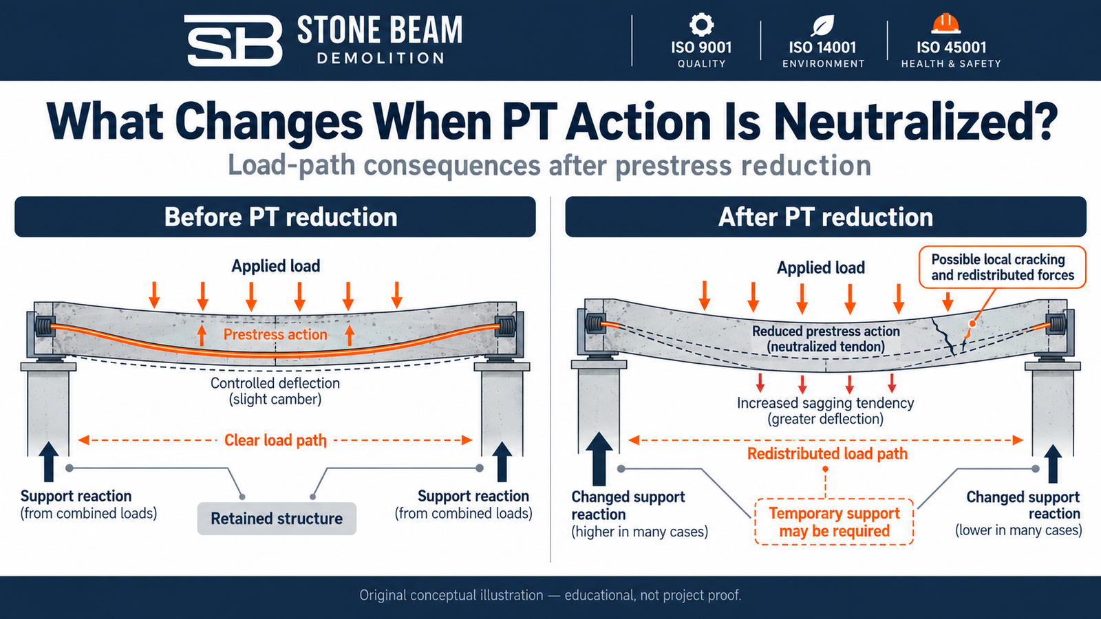
This is why PT demolition should be treated as a staged structural intervention rather than a concrete-breaking task. Existing-structure assessment and temporary stability are central to the decision, not an afterthought. [1][2]
The first question: bonded or unbonded?
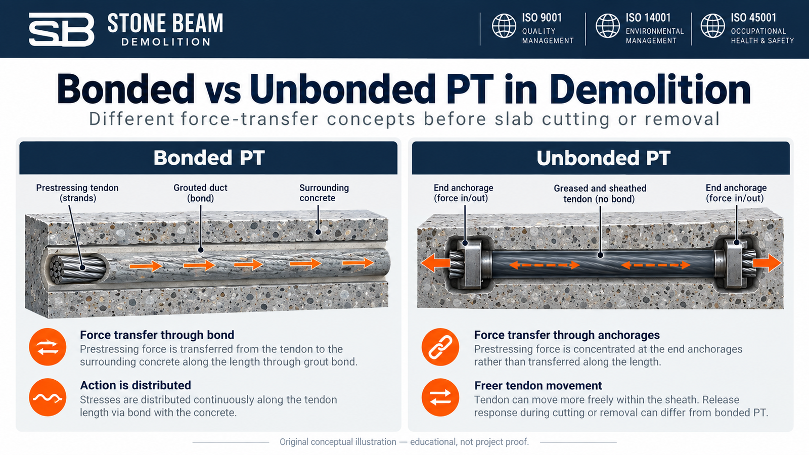
The demolition consequence depends strongly on how the tendon force is transferred. Two broad system types are especially important.
| System | Typical force-transfer concept | Demolition implication |
|---|---|---|
| Unbonded | A greased strand is isolated from the concrete by a sheath and develops its force primarily through anchorages. | Sudden severance can release stored elastic energy and may cause tendon or anchorage movement over a significant tendon length. [3] |
| Bonded | Strands are contained in a duct that is intended to be grouted so force is transferred to the surrounding concrete along the bonded length. | Release may be more localized, but grout voids, local splitting, force redistribution, and retained-structure effects still require engineering assessment. |
| Conservative planning principle |
| If the actual bond/grout condition has not been demonstrated, do not assume the more favorable bonded behavior. GPR can help locate a tendon or duct, but it does not by itself prove that a duct is fully grouted or that a tendon is safe to cut. |
What prestress is doing before demolition starts
The engineering value of the PT system can be explained with a few screening equations. These equations help explain the mechanics; they do not select a field cut coordinate or approve a demolition sequence.
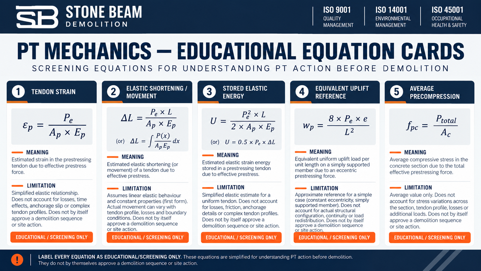
| εp = Pe / (Ap x Ep) εp = tendon strain (dimensionless); Pe = effective prestress force (N); Ap = prestressing steel area (mm²); Ep = tendon modulus (MPa = N/mm²). Units: N / [mm² x N/mm²] = dimensionless. Limitation: idealized linear-elastic relation. It does not predict release distance, anchorage behavior, or site safety. |
|---|
| ΔL = Pe x L / (Ap x Ep) With Pe in N, L in mm, Ap in mm², and Ep in N/mm², ΔL is in mm. For a varying force profile: ΔL = integral[P(x)/(ApEp)] dx. Assumption: tendon force profile, area, and modulus are known, and elastic behavior is a suitable screening model. Limitation: friction, curvature, bond/restraint, and anchorage behavior can materially change actual movement. |
|---|
| U = Pe² x L / (2 x Ap x Ep) For Pe in N, L in mm, Ap in mm², and Ep in N/mm², U is in N·mm; divide by 1000 for joules. Equivalent constant-force form: U = 0.5 x Pe x ΔL. Assumption: idealized linear-elastic constant-force tendon segment. Limitation: energy is a hazard-awareness quantity, not a projectile-speed or travel-distance calculator. |
|---|
| wp = 8 x Pe x e / L² wp = idealized equivalent line uplift for a parabolic tendon. With Pe in N and e, L in mm, wp is N/mm (numerically equal to kN/m). Assumption: idealized parabolic profile with constant effective force over the span. Limitation: screening expression only; it is not a complete analysis of a continuous two-way slab. |
|---|
| fpc = Ptotal / Ac fpc = average precompression. With Ptotal in N and Ac in mm², fpc is N/mm² = MPa. Assumption: the force and concrete area correspond to the same considered strip/section. Limitation: average precompression is only one component of slab behavior and is not a demolition pass/fail threshold. |
|---|
What happens when PT force is reduced or neutralized?
A tendon release can have two different but connected consequences. First, there is a tendon-release problem: stored elastic energy, anchorage behavior, sheath/grout condition, and restraint determine how the tendon may move. Second, there is a structural problem: the slab loses some of the prestress action that was helping it carry load.
Research on cut unbonded tendons confirms that sudden energy release can cause tendon and anchorage movement. The same research also found significant damping from the grease layer in the tested tendons, which is one reason a simple energy calculation cannot be turned into a reliable projectile-distance prediction. [3]
| Do not use stored energy as a projectile calculator |
| The energy equation is useful for hazard awareness and comparison. Actual tendon motion depends on system type, tendon length, grease/sheath friction, curvature, corrosion, anchorage wedges, confinement, and other project conditions. |
What must be known before any slab intervention?
The quality of the demolition decision depends on the quality of the pre-demolition information. Before a slab zone is cut or removed, the project team should resolve the information that materially affects the load path and the PT release strategy.
- Latest structural, PT shop, and as-built drawings where available, including slab spans, supports, columns, openings, and retained zones.
- Tendon layout, profile and live/dead-end information where it is relevant to the system.
- Stressing, grouting and repair records where available.
- Field mapping / scanning evidence to map likely tendon, duct and reinforcement locations, recognizing the limitations and interpretation uncertainty of the selected technique.
- The actual work scope: complete bay removal, partial opening, local modification or a retained slab that must remain in service.
- Temporary construction/demolition loads, access above and below the slab, panel-removal constraints and lifting interface.
- The responsible structural, PT, temporary works and lifting designers/reviewers for the decisions they own.
General demolition guidance also emphasizes pre-work structural information, competent assessment and planned temporary stability where the structure may be altered, or its load path changed. [4]
Why there is no universal “best” tendon cut point
A simple internal-cut model can explain why a location near mid-length is mechanically interesting. If the tendon force and stiffness are idealized as uniform, cutting at a fraction r = x/L of the length gives a simple theoretical movement split:
| ΔLleft = r x ΔL | ΔLright = (1 – r) x ΔL | r = x/L Illustrative equal-property segment model: r is dimensionless, and the two terms partition the idealized released elastic shortening. Limitation: this is not a prediction of actual strand travel. It omits real force variation, friction, bond, anchorage restraint, support geometry, openings and temporary works. |
|---|
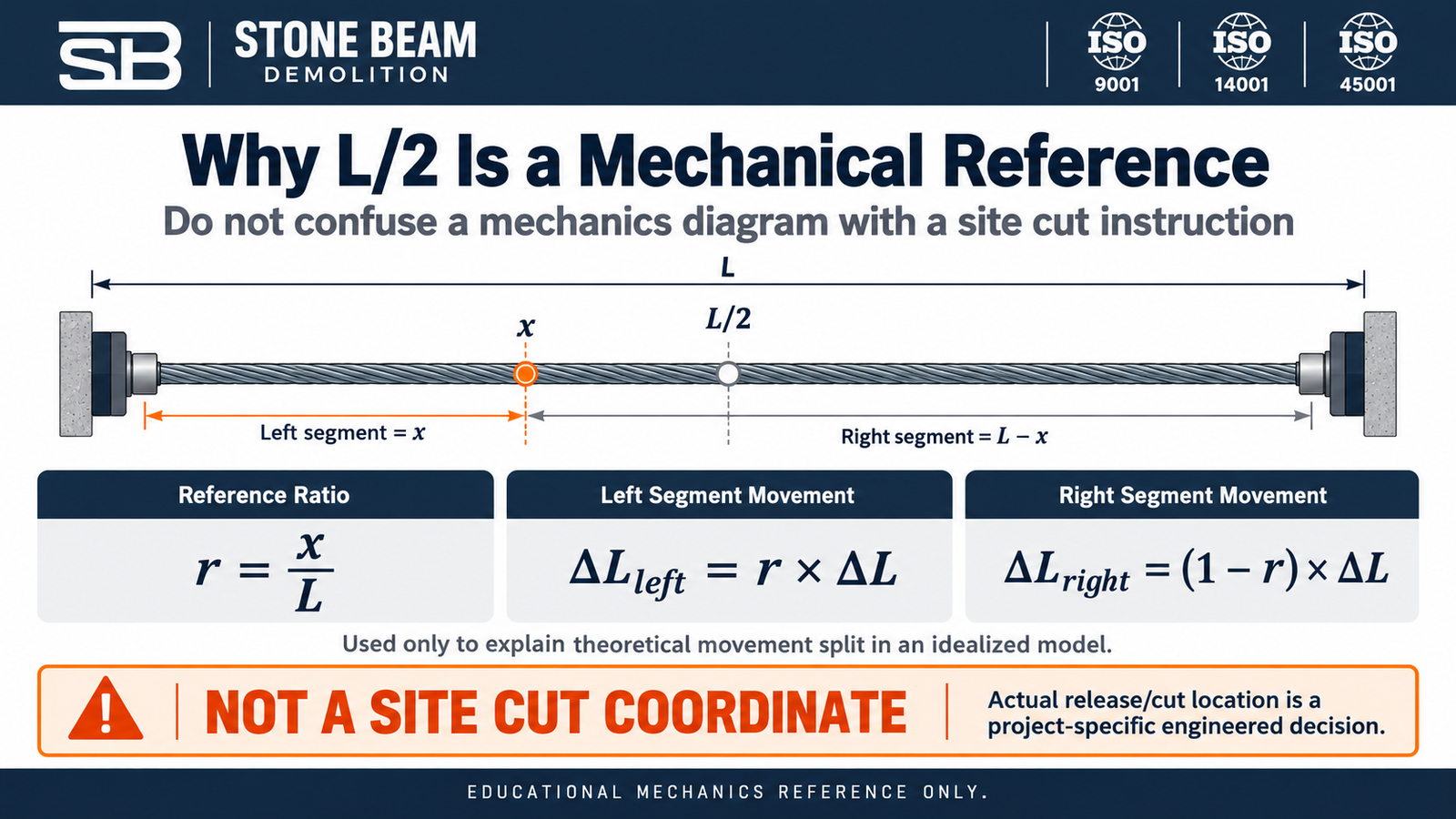
Foreign demolition guidance from the Hong Kong Buildings Department has historically noted midspan cutting of unbonded tendons as a way that can reduce shoot-off effects in appropriate circumstances. That is useful comparative evidence, but it is not a UAE site rule, and it does not make midspan the universally “safest” execution point. The same demolition problem still requires project-specific engineering. [5]
| Public rule for cut-location discussions |
| Use L/2, L/3, or L/4 only to explain mechanics or compare theoretical movement. The actual release/crossing location is an engineered decision based on the PT system, supports, columns, load path, slab condition, openings, temporary works, access, and selected specialist release method. |
Why “long direction first” or “short direction first” is not a rule
The same principle applies to sequence. PT slabs can use banded, distributed, dual-banded, one-way, or beam-supported arrangements. A sequence observed on one project does not become a general demolition law for another slab.
| Decision variable | Why it matters |
|---|---|
| Load path and support system | Determines which strips, supports, and retained zones are structurally critical at each stage. |
| Tendon layout | Banded or column-line tendons may be particularly important to support-zone behavior. |
| Retained vs removed structure | A permanent opening has different structural objectives from complete slab demolition. |
| Temporary works | Supports can deliberately change the load path and stage capacity. |
| Construction loads and access | Sawing equipment, workers, debris, and lifting operations can change stage demand. |
| Monitoring and verification | Do not proceed to the next stage if observed behavior does not match the accepted stage assumptions. |
| Sequence rule |
| LOAD PATH FIRST > TENDON LAYOUT > TEMPORARY WORKS > SPAN LENGTH. There is no universal long-direction-first, short-direction-first, distributed-first or banded-last rule. |
Controlled tendon release is a specialist engineering decision
The article deliberately does not prescribe a tendon-by-tendon detensioning procedure. The appropriate release method depends on the identified system and the condition of the actual anchorages, tendons, grout/sheathing, retained structure and access.
Anchorage accessibility and condition are inputs a PT specialist may consider when selecting a controlled release strategy. This article does not recommend anchor manipulation, wedge removal, cutting at an anchorage or any other site procedure. If internal neutralization or another system-specific intervention is considered, the competent structural/PT team must make the choice and support it with the relevant temporary-works and stage checks.
| What this article does not provide |
| This article does not provide DIY anchor manipulation, wedge removal, heating/annealing temperature, fixed shield thickness, exclusion-zone dimension, prop spacing, tendon batch size, or a universal release sequence. Those are project- and system-specific engineering decisions. |
Temporary works: protecting the changing load path
Shoring and temporary works are not simply a safety precaution around PT demolition. They may be part of the temporary structural system that replaces or redistributes the load path while prestress is being altered.
The temporary works designer needs to consider the loads and stages that actually occur during demolition: slab self-weight, retained dead/live loads, equipment, workers, local panel support, redistribution to adjacent spans, cutting operations and lifting/removal interfaces. Temporary support should be designed, installed, checked and maintained for the foreseeable loads at the relevant demolition stage. [2][4]
Full slab demolition and partial openings are different engineering problems
A complete demolition zone and a permanent opening in a retained PT slab should not be treated as the same problem.
| Complete removal / demolition | Permanent opening / retained slab |
|---|---|
| The objective is to neutralize/remove PT action in a controlled demolition zone and maintain stability until the concrete is removed. | The remaining slab must continue to perform after the opening exists. |
| The release strategy is integrated with temporary works, panelization, and removal. | The design may need tendon termination, re-anchorage, strengthening, replacement force paths, or other permanent structural measures. |
| The end state is removal of the affected slab zone. | The end state is a modified structure that remains in service and requires design verification. |
PTI guidance for openings in existing unbonded PT slabs emphasizes both structural analysis and construction planning. It is useful for retained-opening problems, but it should not be misused as a generic demolition sequence. [6]
The PT demolition evidence and hold-point chain
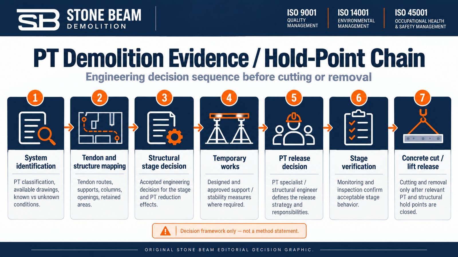
A strong PT demolition package makes the evidence visible. The owner and consultant should be able to see what information was used, who made each engineering decision, and what had to be verified before the next stage was released.
| Hold point | Evidence / decision expected |
|---|---|
| 1. System identification | PT system classification; available drawings/records; known and unknown conditions separated. |
| 2. Tendon and structure mapping | Tendon routes, supports, columns, openings and retained areas mapped to the demolition scope. |
| 3. Structural stage decision | Accepted analysis/engineering decision for the stage, including effects of PT reduction and temporary loads. |
| 4. Temporary works | Designed and approved temporary support/stability measures where required. |
| 5. PT release decision | PT specialist / structural engineer defines the selected release strategy and responsibilities. |
| 6. Stage verification | Monitoring and inspection confirm the structure and supports remain within the accepted stage behavior. |
| 7. Concrete cut / lift release | Concrete panel cutting and removal proceeds only after the relevant PT and structural hold points are closed. |
What should be monitored during staged demolition?
Monitoring is project-specific, but its purpose is consistent: verify that the actual structure is behaving in a way that is compatible with the accepted demolition stage. Typical observations may include slab deflection, crack development, anchorage or local slab movement, temporary-support behavior, and any unexpected tendon-release response.
Universal numeric stop-work thresholds should not be copied from another project. Trigger values, where required, must be selected for the actual structure, instrumentation,n and engineering assumptions.
What owners and consultants should request before approving cutting
- A clearly marked demolition/removal scope and the retained-structure boundaries.
- The tendon map and the basis used to classify the PT system and bond/grout condition.
- A staged structural decision that addresses the changing load path, not only the saw-cut layout.
- Temporary works design/responsibility where the slab needs support or load redistribution during the works.
- The PT specialist release/neutralization method and the hold points that prove the stage is ready to proceed.
- The panel support, lifting, and removal interface where cut panels will be handled as suspended loads.
- Monitoring, inspection, and stage-verification records appropriate to the risk and retained structure.
- The applicable authority/consultant submissions for the project jurisdiction, without assuming that one Dubai authority checklist applies everywhere.
Dubai regulatory context
Dubai’s construction-safety framework is governed by Decree No. 19 of 2025, which applies the emirate-wide construction-safety framework across Dubai and makes the adopted safety code binding on contractors and engineering consultancies. Administrative Resolution No. 112 of 2026 adopts the Safety Guide referenced by that Decree. These are broad construction-safety requirements; they do not prescribe a universal PT tendon release method. [7][8]
Where Dubai Development Authority jurisdiction applies, the current demolition-permit service lists a method statement, project-specific HSE/emergency plan, risk assessments, and a study of the effect of demolition on surrounding buildings among the required submission documents. That DDA checklist should not be generalized to every Dubai jurisdiction without checking the competent authority for the actual plot. [9]
Information to send for a PT slab demolition review
For a useful scope and quotation review, send the information that changes feasibility, responsibility, and execution planning:
- Project location and approving jurisdiction.
- Latest structural/PT/shop/as-built drawings available.
- Slab plan, spans, thickness, support/column layout, and marked removal boundary.
- Full slab/bay removal, permanent opening, or local modification scope.
- Known tendon type, bond/grout status, and live/dead-end information, if available.
- Existing stressing, grouting, repair, GPR/NDT or tendon-mapping records.
- Retained/occupied areas, adjacent assets and access above/below the slab.
- Temporary works and lifting responsibilities, access constraints and removal route.
- Required consultant/client submissions, work windows and handover records.
| Next step with Stone Beam |
| Send the slab/PT drawings, marked removal scope, support layout, any tendon/scan information, project location and access constraints. Stone Beam can use that information to define the demolition/PT interface and prepare a project-specific scope and quotation without pretending that a universal cut point or release sequence applies. |
Final engineering takeaway
Post-tensioned slab demolition is a specialized structural problem that combines tendon mechanics, existing-structure assessment, temporary works and staged risk control. A scan may tell you where a tendon is. An equation may explain how prestress behaves. Neither one, by itself, tells you where to cut.
A defensible decision chain is: identify the system, map the tendons and supports, establish the temporary load path, select the specialist release strategy, verify each stage, and only then release concrete cutting and lifting. This is a decision/hold-point framework, not a site-ready detensioning method statement. That distinction is what separates treatment of a PT slab from ordinary concrete removal.
Engineering sources cited in this article
[1] ACI/PTI CODE-320-25 Post-Tensioned Structural Concrete – Code Requirements and Commentary – source
[2] ACI CODE-562-25 Assessment, Repair, and Rehabilitation of Existing Concrete Structures – Code Requirements and Commentary – source
[3] Williams & Waldron (1989) Dynamic Response of Unbonded Prestressing Tendons Cut During Demolition – source
[4] UK HSE Structural stability during alteration, demolition and dismantling – source
[5] Hong Kong Buildings Department Code of Practice for Demolition of Buildings 2004 (with published amendments listed by Buildings Department) – source
[6] Post-Tensioning Institute PTI DC80.2-10 Guide for Creating Openings and Penetrations in Existing Slabs with Unbonded Post-Tensioning – source
[7] Dubai Legislation Decree No. (19) of 2025 Concerning Safety in Construction Works in the Emirate of Dubai – source
[8] Dubai Legislation Administrative Resolution No. (112) of 2026 adopting the Construction Works Safety Guide – source
[9] Dubai Development Authority Demolition Permit service – source