



A good concrete ground-penetrating radar (GPR) report answers five practical questions: Where was the scan carried out? What was detected? How reliable is the estimated depth? Which areas were not covered? And how do the findings relate to the proposed core hole? Begin with the scan ID and marked drawing, then check the plan view, cross-sections, material assumptions, and the operator’s findings.
In a Dubai fit-out or structural alteration, the report is one input to the engineer’s decision before core drilling. It does not itself approve an opening. The guide below shows how to read a PROFIS-style export, when to use another scanning method, and what to send the project team so they can act on the investigation.
For a site survey, see Stone Beam’s concrete scanning and GPR service in Dubai.
By Eng. Awad Ashour, Founder & CEO, Stone Beam Demolition
First Check: Is It a Scan Image or a Complete Survey Report?
First, decide whether you have received a software-generated scan export or a complete survey submission. The export typically contains the radar image, an identifier, selected coordinates, and comments; the submission connects those results to drawings, actual scan coverage, and the engineering question. Both are useful, but they answer different questions.
Software export versus survey report
| Information | Individual scan export | Review-ready survey package |
|---|---|---|
| Scan identification | May include a scan ID or filename | Links each scan to an identifiable location |
| Radar image | May display plan and sectional views | Explains relevant findings and their interpretation |
| Coordinates | May show software coordinates or cursor readings | Relates findings to a defined site reference |
| Survey coverage | May show the recorded scan window | Identifies the actual covered area and exclusions |
| Depth information | May display estimated or selected values | Explains depth assumptions and uncertainty |
| Operator comments | May contain a short observation | Separates confirmed observations from interpretation |
| Proposed opening | Not necessarily identified | Connects the findings to the relevant work reference |
| Unresolved issues | May not be explicitly listed | Records limitations and outstanding questions |
Agree the reporting deliverables at the RFQ stage; an image export and a location-linked investigation report are different items.
Why this distinction matters
Consider a contractor who receives a colourful reinforcement image with several coordinate values but no drawing reference.
Without a drawing grid or marked location, the contractor cannot match that image to the opening. Ask for the survey reference and coverage plan before sending the evidence for design review. The problem is traceability, not necessarily the scan itself.
How to Read the Main Fields in a GPR Scan Report
A PROFIS-style export can display Scan File, Scan Name, Date/Time, X, Y, Z, Thickness, Concrete parameter, and Method. Read the values with the original scan orientation and processing settings, rather than treating every number as a certified site measurement. Field labels and meaning depend on the software version and selected view.
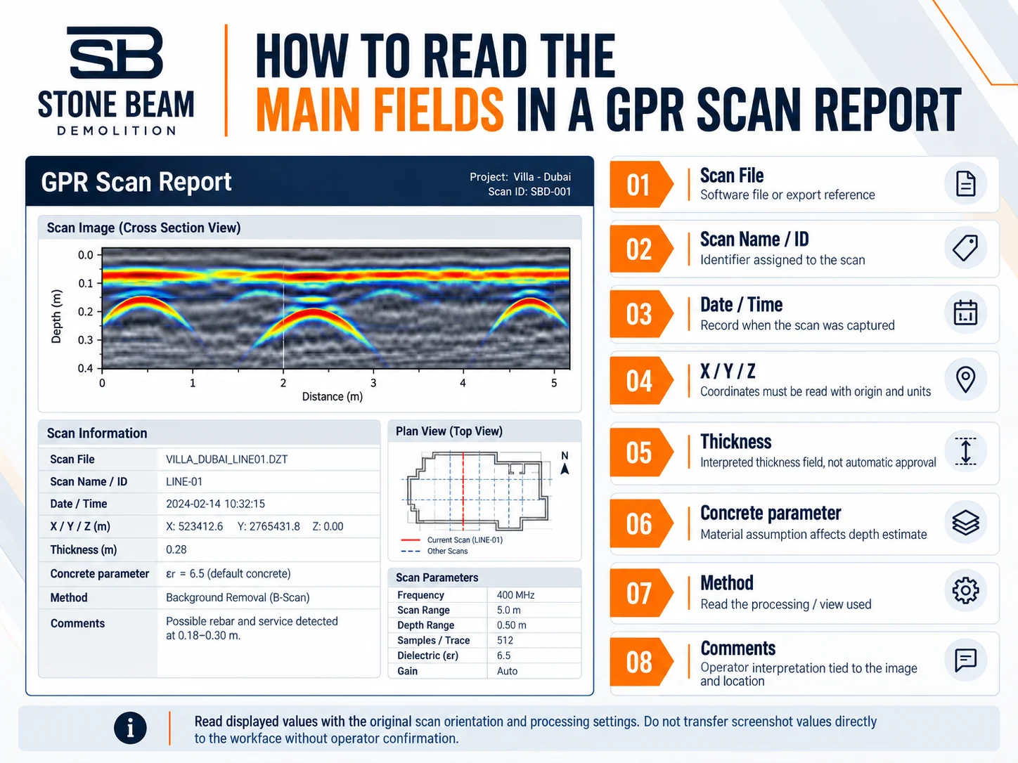
PROFIS report field guide
| Report field | What it tells you | What must be verified |
|---|---|---|
| Scan File | The digital dataset reference | Whether the corresponding record is available |
| Scan Name / ID | An identifier assigned to the scan | Which physical area it represents |
| Date / Time | When the dataset was recorded | Whether it corresponds to the relevant survey visit |
| Project / Object | Entered project and element information | Whether it identifies the correct slab, wall or other element |
| Comment | An operator-entered observation | Whether the observation is supported and appropriately qualified |
| X / Y | Displayed coordinates or selected positions | Origin, orientation and units |
| Z | A software-defined coordinate or depth-related reading | Its precise meaning in that report view |
| Thickness | A displayed dimension or parameter | Whether it is entered, estimated, or independently verified |
| Concrete Parameter | A material value or assumption used in processing | Whether the selected value is appropriate and how it was established |
| Processing Method | The software analysis setting or method | Which assumptions influence the displayed results |
What do X, Y, and Z mean?
In a typical export, X and Y describe displayed locations in the scan’s coordinate system; Z is a depth-related value or selected point, bzjretlcq vz the software view. The reviewer needs the axis origin, units, and operator confirmation before converting those values into marks on the slab. Do not copy X/Y/Z from a screenshot directly onto the workface.
Does the Thickness field prove slab thickness?
A field labelled Thickness is a displayed parameter whose source must be checked. The operator should state whether it came from a selected interpretation, a known reference, or another setting. For a slab-thickness investigation, request a result that identifies the reference faces, method,d and uncertainty; the existence of the field alone is not that result.
How should operator comments be read?
Treat the comment as the operator’s interpretation. A note such as “steel responses observed” is useful when tied to a location and image; it does not classify every concealed item. Ask the surveyor to distinguish an observed response, a suspected object, and an area that could not be interpreted.
Example field reports:
The PDFs below are real PROFIS Detection report examples provided for educational review.
A scan report supports technical assessment but does not itself authorise core drilling or structural alteration.
How to Understand GPR Plan Views and Cross-sectional Images
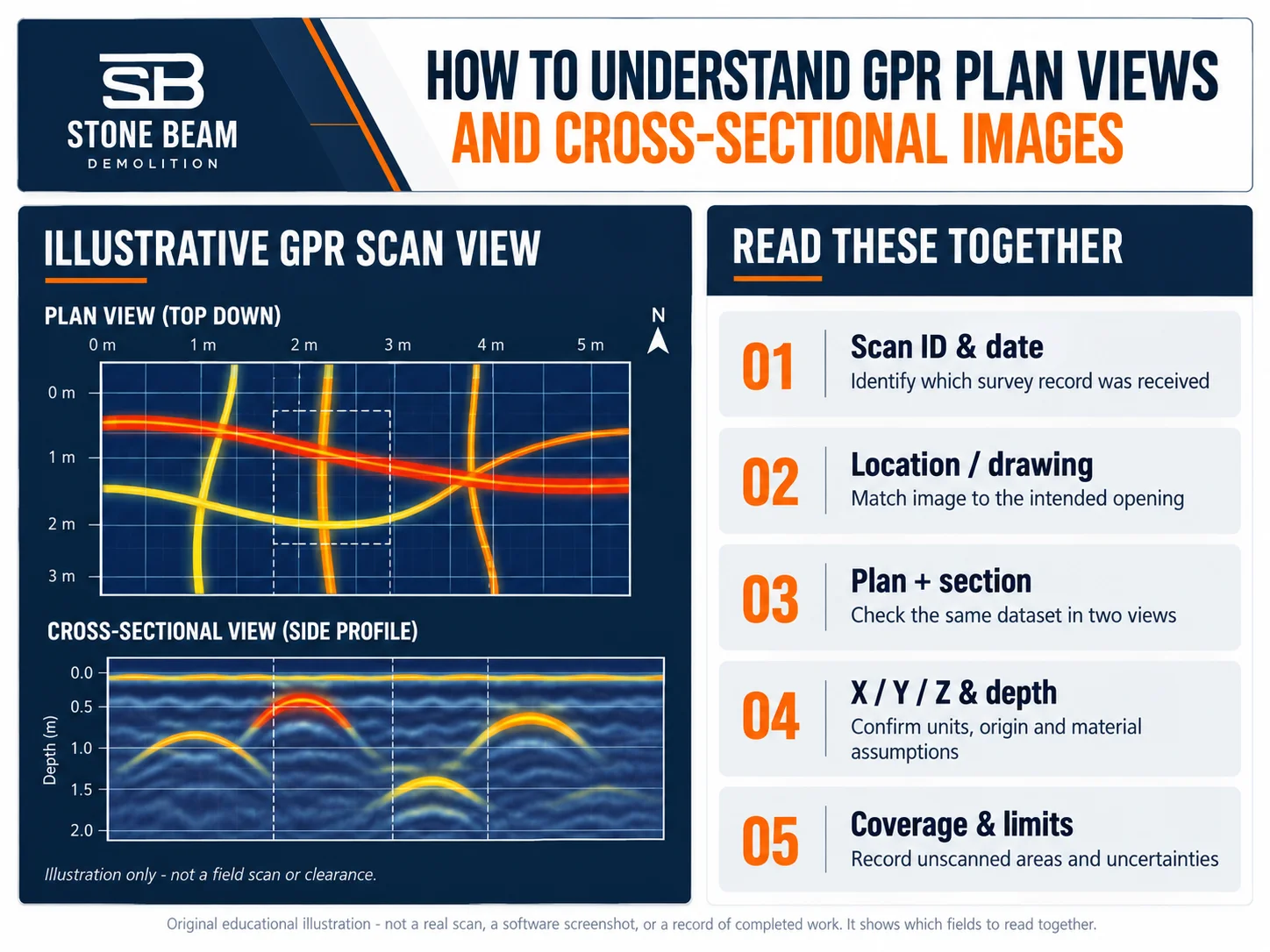
Radar images represent processed electromagnetic reflections. They are not photographs of embedded reinforcement or services.
The appearance of an object depends partly on its orientation relative to the survey path, material characteristics, and the way the recorded data is displayed.
Plan-view images
Plan views help show the arrangement and continuity of interpreted reflections across the recorded survey area.
Patterns may be consistent with reinforcement grids, embedded-object routes or other interfaces.
However, a continuous coloured line is not automatically proof of a particular object’s identity.
The interpretation should consider the survey direction, related cross-sections, other available information and the operator’s observations.
Cross-sectional images
Cross-sectional radar views show reflected responses along a scan path, represented against a travel-time or interpreted depth scale.
An object crossing a survey line may create a curved or hyperbolic reflection pattern. Other features or orientations may produce different responses.
These patterns assist interpretation but do not necessarily represent the concealed object’s physical shape.
What do red, yellow and blue colours mean?
Colours represent processed signal information and display contrast, not a universal material code: red is not automatically rebar and blue is not automatically a void. Compare the plan with cross-sections and the operator’s interpretation before classifying a response.
Do different images mean separate confirmation?
A plan and a cross-section can be two views of one dataset. This improves interpretation, but it is not independent verification. If confirmation is required, record the separate survey pass, instrument, or alternative method used.
Understanding Depth, Concrete Permittivity and Measurement Uncertainty
Estimated depth is one of the most useful — and easily misunderstood — parts of a GPR report.
Radar determines responses through electromagnetic-wave behaviour. Converting a recorded response into an estimated physical depth requires assumptions about how those waves travel through the investigated material.
What is concrete permittivity?
The relative permittivity of concrete (εr) influences radar-wave velocity. In a simplified low-loss model, v ≈ c / √εr and the reflector depth is d ≈ c × t / (2√εr), where c is the speed of light and t is the recorded two-way travel time. This is a teaching relationship, not a site calibration method.
For the same travel time, an illustrative setting of εr = 9 produces a depth estimate approximately 18% smaller than εr = 6. Those figures illustrate sensitivity; they are not a recommended concrete-permittivity range or an interpretation of any project’s setting. Moisture and other material properties change the effective response. Hilti’s PS 1000 guidance therefore recommends checking concrete characteristics or a known reference depth when improving depth estimates.
Questions to ask about reported depths
Before relying on an estimated depth, check:
- Is the value associated with a specific interpreted object?
- Which scanned face is used as the reference?
- What material parameters were assumed?
- Was a known reference depth available?
- Was the value adjusted during software analysis?
- Is the result presented as an estimate or a verified measurement?
- Could the uncertainty affect the proposed engineering decision?
The reviewer should be particularly cautious where dense reinforcement, multiple layers, or material interfaces complicate interpretation.
Object depth is not the same as concrete cover or slab thickness
These terms answer different questions.
- Object depth: an interpreted distance from a reference surface to a detected response.
- Concrete cover: the distance from the concrete surface to the nearest outer surface of the reinforcing bar.
- Slab thickness: the overall dimension of the structural element between its relevant faces.
A GPR depth reading does not, on its own, provide the same measurement as a dedicated cover-meter result.
How deep can the Hilti PS 1000 scan?
Hilti’s current UAE PS 1000 product technical data lists 300 mm as the maximum detection depth for object localisation, with nominal depth-indication accuracy of ±10 mm below 100 mm and ±15% above 100 mm. These are manufacturer specifications subject to site conditions. Dense reinforcement, moisture, and the element build-up can limit the effective depth or confidence achieved on site. Source: Hilti UAE PS 1000 technical data.
What Can Make a GPR Report Difficult to Interpret?
The effectiveness of concrete scanning depends on the actual site and material conditions.
Hilti’s PS 1000 guidance identifies several situations that may complicate detection or interpretation.
| Condition | Potential limitation | What the report should clarify |
|---|---|---|
| Rough concrete surface | Inconsistent scanner contact can affect readings | Surface condition and relevant allowance |
| Reinforcement near an element edge | Edge targets may produce weaker or incomplete responses | Coverage boundaries and uncertainty |
| Dense reinforcement | Stronger upper responses may obscure deeper features | Interpretation limits and possible unresolved objects |
| Steel near PVC conduits | Non-metallic objects may appear less distinctly | Uncertain object identity |
| Multiple reinforcement layers | Closely spaced targets may be difficult to resolve | Possible overlap and depth limitations |
| Damp or heterogeneous concrete | Material behaviour may alter radar response | Relevant environmental and material assumptions |
| Metal-backed finishes or conductive layers | Strong reflections or attenuation may obstruct investigation | Areas affected and need for additional evidence |
| Restricted physical access | The full intended zone may not have been surveyed | Exact unscanned areas |
Why survey boundaries are important
A report should identify the effective scanned zone, not just the location of the scanner or the dimensions of an image.
A nearby obstruction, inaccessible edge or unsuitable surface can leave an area uninvestigated.
The reviewer must not extend conclusions into those areas merely because they are close to a surveyed zone.
When might another investigation be needed?
Where relevant uncertainty remains, the responsible specialist may consider another accessible face, further analysis or an appropriate complementary investigation.
The method should be selected according to the actual question and site conditions, rather than assumed to be necessary for every project.
A finding of uncertainty is a legitimate technical outcome and should be clearly recorded.
GPR vs Ferroscan, Cover Meter and X-ray: Which Question Does Each Answer?
The instruments are not interchangeable. Choose the investigation method to match the question instead of ordering “concrete scanning” without specifying the required finding.
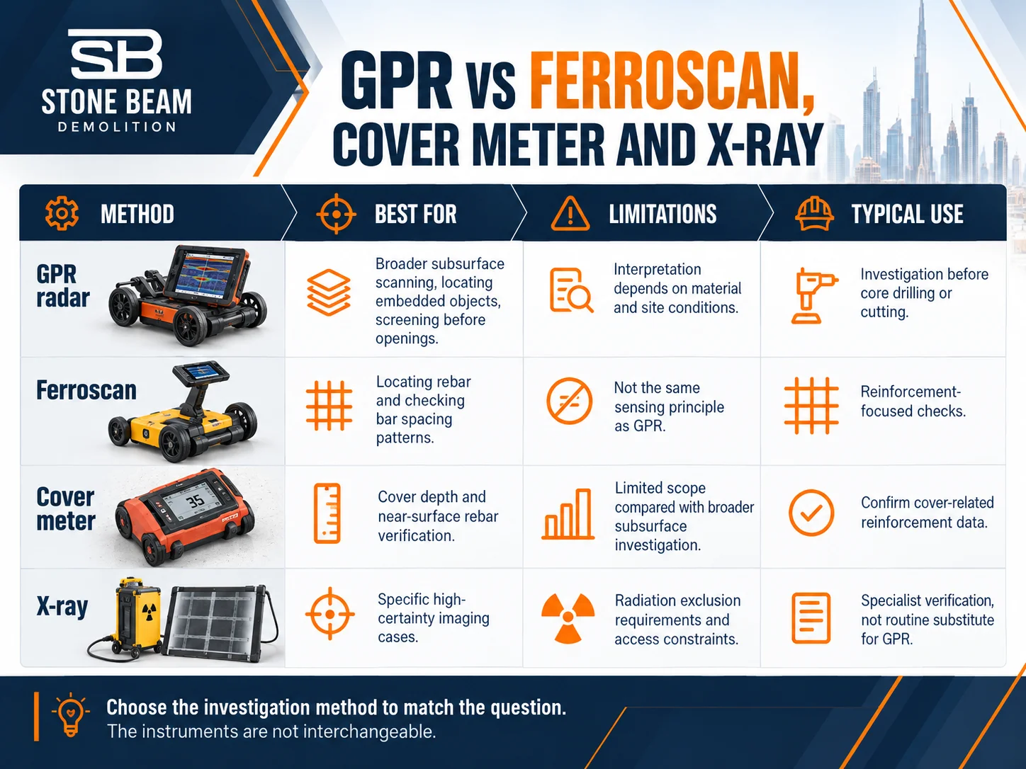
| Method | Best-suited investigation | Important limitation | Typical decision trigger |
|---|---|---|---|
| GPR radar | Mapping multiple reflections, possible reinforcement layers and other embedded features | Object identity and depth depend on signal conditions and interpretation | A proposed opening with uncertain embedded features |
| Ferroscan / electromagnetic-induction rebar scanner | Rebar position, top-layer cover and, under suitable conditions, bar-size estimation | Primarily targets ferromagnetic reinforcement; crowded arrangements affect results | A cover survey or top-layer reinforcement question |
| X-ray / radiography by an authorised specialist | Imaging concealed features where geometry, access and radiation controls allow | Radiation exclusion requirements and access constraints; not a routine substitute for GPR | An unresolved location requiring a specialist radiographic assessment |
| Controlled exposure / exploratory verification | Directly identifying a feature where a designer authorises investigation | Intrusive; can damage reinforcement, PT or services if poorly planned | Ambiguous evidence that cannot be resolved non-destructively |
A pilot hole should not be used as an informal “confirmation” in a suspected PT or live-service zone. The structural, PT, and services specialists must determine whether any intrusive verification is permissible. Hilti describes the PS 300 Ferroscan as a rebar-location and cover-measurement system; it is not the same sensing principle as GPR.
Worked Example: Reviewing an Incomplete Concrete Scan Report
This fictional example shows how to identify missing information in an incoming report.
Information received
A project engineer receives a software-exported scan image with the following information:
| Item | Example status |
|---|---|
| Scan ID | EX-SCAN-A |
| Element | Existing concrete slab |
| Radar image | Available |
| X / Y / Z readings | Displayed |
| Thickness field | Displayed |
| Operator note | Steel-related responses observed |
| Survey location drawing | Not supplied |
| Effective scan coverage | Not defined |
| Instrument assumptions | Not documented |
| Proposed core reference | Not linked |
| Limitations note | Not supplied |
What can the engineer conclude?
The engineer can confirm that an identifiable scan export was submitted and that it contains radar images and an operator observation.
The available information does not establish the exact work-area coverage, the basis of the displayed dimensions, or whether the proposed penetration lies within the investigation.
It also does not confirm that all relevant embedded services or structural features have been excluded.
What should happen next?
| Missing information | Clarification required from |
|---|---|
| Scan position and orientation | Survey team |
| Survey boundary and accessible faces | Survey team / main contractor |
| Meaning of displayed depth-related values | Survey specialist |
| Relationship to proposed opening | Project coordinator / designer |
| Relevant structural and PT information | Responsible structural engineer / PT specialist |
| Suspected concealed services | Relevant MEP or asset-owner representative |
Document-review outcome: CLARIFICATION REQUIRED.
This means the supplied records are insufficient for the particular review. The surveyor and project team can now close the specific information gaps before the report is resubmitted.
Once the missing information is provided, the relevant specialists can determine whether further investigation or design review is required.
GPR Scan Report Review Checklist
The checklist below helps a receiving engineer or contractor identify whether a report contains the information needed for the next review.
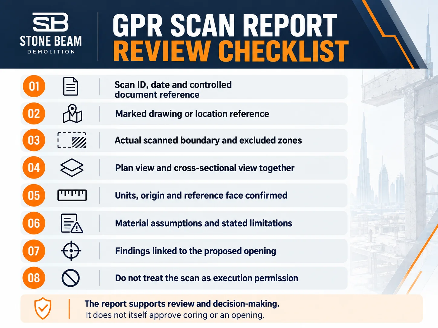
Use the checklist to identify missing documents and the correct reviewer.
| Review requirement | Acceptable documentary evidence | If missing |
|---|---|---|
| Correct survey location | Marked plan with element and location reference | Request location clarification |
| Survey identification | Scan ID, date, and controlled document reference | Obtain traceable records |
| Coverage and limits | Actual scanned boundary and excluded zones | Request survey coverage information |
| Findings | Annotated views and qualified interpretation | Ask the survey specialist to clarify |
| Depth basis | Reference surface, assumptions, and relevant calibration evidence | Clarify measurement uncertainty |
| Proposed opening link | Opening ID and current drawing revision | Coordinate with the project designer |
| Unresolved features | Explicit limitation or uncertainty record | Refer for appropriate specialist assessment |
| Report version | Revision and date consistent with the current work | Reconcile revised documents |
| Engineering assessment | Separate review by the responsible engineer | Keep the execution decision pending |
| Relevant work release | Appropriate project documentation and authorisation | Do not treat the scan as execution permission |
How to use the checklist
The reviewer should identify whether an item is documented, requires clarification, or needs an additional specialist decision.
The report should not be rejected merely because an uncertain feature exists. Its limitations must instead be considered against the purpose of the investigation.
Equally, a report containing every administrative field may still require more technical investigation.
Completeness of documentation and engineering acceptability are separate questions.
Scan-to-Core Register: Linking the Report to the Proposed Opening
When a project involves multiple core holes or openings, it is useful to maintain a document register that links each proposed penetration to the relevant investigation.
This reduces the risk of using a report for the wrong location, drawing revision, or element.
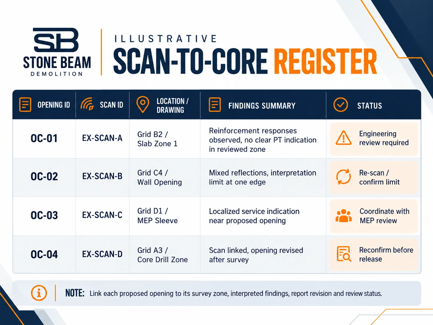
Illustrative Scan-to-Core Register
Illustrative example — three proposed openings at different documentation stages:
| Opening ID | Element / drawing | Survey record | Limitation / status | Engineering review |
|---|---|---|---|---|
| EX-A | Slab / Drawing A | EX-SCAN-A | Location clarification required | Pending |
| EX-B | Wall / Drawing B | EX-SCAN-B | Coverage to be checked | Pending |
| EX-C | Slab / Drawing C | No matched survey record | Investigation evidence missing | Pending |
A real register should also record the proposed opening’s current geometry, survey-zone reference, report revision, applicable MEP review, and the separate execution status.
What if the opening changes after scanning?
A change in opening position, size, or design can make the original investigation partly or wholly irrelevant to the revised work.
The project team should preserve the original survey record, document the change, and request confirmation of whether the new requirement is adequately covered.
A register should make those changes visible instead of relying on informal instructions.
How does this help the cutting contractor?
The register gives the receiving contractor a traceable record of which survey and engineering documents relate to the released work scope.
It helps the receiving team check the current revision before the released work is passed to the coring contractor.
For physical execution requirements, visit Stone Beam’s core drilling and core cutting service in Dubai.
Who Is Responsible for Interpreting and Approving the Next Step?
Survey findings should be reviewed by the appropriate parties according to their responsibilities.
The survey provider reports the agreed investigation. The responsible structural engineer evaluates the proposed structural alteration. MEP specialists address relevant concealed-service information.
Where post-tensioning is involved, additional specialist assessment may be required.
| Party | Relevant responsibility |
|---|---|
| Client / main contractor | Define the work, provide information and coordinate the project interfaces |
| GPR survey specialist | Record survey coverage, findings, assumptions and limitations |
| Structural engineer | Assess the proposed alteration and determine relevant design requirements |
| PT specialist, if applicable | Provide PT-specific investigation and assessment |
| MEP / asset-owner specialist | Review concealed-service information and coordinate relevant clearance |
| Core drilling / cutting contractor | Execute only against the appropriate released work scope and site controls |
What if a possible PT tendon appears in the scan?
A GPR response may support interpretation of a possible tendon route.
Tendon position is only one part of the PT assessment. Route the record to the appointed structural engineer and PT specialist for the design decision.
Stone Beam’s post-tensioned slab demolition guide explains the wider responsibilities and information required before PT-related alteration works.
A useful information chain
Define the opening → identify survey evidence → record interpretation and limitations → obtain engineering assessment → document the separate work release.
If the location, interpretation or release changes, update the register so the latest work package remains traceable.
Concrete Scanning for Dubai Fit-Outs, Towers and Managed Buildings
For a Dubai project, the technical scan is only one handover in a wider fit-out or alteration package. Before commissioning the scan, ask the main contractor or building management who controls access, whether the area is occupied, which drawing revision governs, and who accepts the report. A scanning report that cannot be matched to the current consultant-approved opening drawing may delay the decision even if the radar images are clear.
Where post-tensioned concrete is suspected, obtain the available PT and structural information and identify the appointed structural engineer and PT specialist. Where electrical, water, communications, or other services are suspected, the relevant MEP and asset-owner representatives must establish whether separate verification or clearances are required. DEWA or telecom interfaces are project-dependent, not evidence that every slab contains those utilities or that every core requires the same NOC.
A practical handover in a managed building is: marked opening schedule → access and PTW arrangements → traceable scan/report → engineering and MEP review where applicable → separate released work package. Confirm the applicable project and site procedures with the main contractor; Dubai’s construction-safety framework does not create a blanket rule that GPR must precede every core. Dubai construction safety framework.
What Should You Request When Ordering a Concrete GPR Survey?
Before appointing a scanning contractor, define the question the investigation must answer.
Agree the deliverables in the RFQ rather than assuming that a colour scan image includes the complete reporting package.
| Item | What to agree |
|---|---|
| Survey objective | What concealed feature or condition needs investigation? |
| Survey boundaries | Which element, surface, and area will be examined? |
| Available information | Which structural, PT, or MEP drawings are supplied? |
| Site access | Which faces are accessible and what preparation is needed? |
| Surface markings | Are markings required, and how will they be referenced? |
| Scan images | Which annotated views or output formats are required? |
| Technical report | Are interpretations, limitations, and a written summary included? |
| Opening references | Should the report reference individual proposed penetrations? |
| Additional investigation | How will uncertain or inaccessible areas be addressed? |
| Engineering review | Which party provides the separate structural or PT assessment? |
| Follow-on works | Are coring, cutting or reinstatement separate packages? |
The survey scope should identify confirmed deliverables and separately instructed work.
What should you send Stone Beam?
For a concrete scanning enquiry, provide:
- The project location and the concrete element to be investigated.
- Marked drawings identifying the intended survey area.
- Proposed core-hole or opening details where available.
- Structural and MEP information relevant to the element.
- Any known post-tensioning or concealed-service concerns.
- Photographs showing surface condition, access and obstructions.
- The required format of markings, scan images or technical report.
Stone Beam Demolition is a Dubai-based contractor specialising in demolition, concrete cutting and site enabling works.
We have been appointed for scanning, reporting, and coring packages in existing commercial and residential buildings. Our recommended handover links each proposed opening ID to its survey zone, interpreted findings, report revision, and the engineer’s decision, so the main contractor can coordinate the subsequent work package.
About the author
Eng. Awad Ashour is the founder and CEO of Stone Beam Demolition. A civil engineer with more than 15 years of demolition experience in the UAE, he has led villa, building, basement, and enabling-works demolition and oversees the company’s engineering and method planning. He focuses on making technical surveys and engineering handovers useful for controlled work planning.
Frequently Asked Questions
Is a Hilti PROFIS Detection export a complete scanning report?
Not necessarily. A software export can contain useful scan data and selected parameters, but the project may also require a location plan, coverage record, interpretation notes, and documented limitations. Check the agreed deliverables and the purpose of the review.
Can I use the Z value in a GPR report as the exact depth of a rebar?
Use it only after confirming the reference face, field definition, and material settings with the scan operator. The displayed value is an interpreted reading, not a substitute for the required engineering assessment.
Does a GPR scan prove that no MEP services exist in the concrete?
It records what the operator could interpret within the inspected area. Confirm suspected services through drawings and the responsible MEP or asset-owner specialist.
Why might two scans of the same slab look different?
They may cover different zones, follow different survey directions, or use different processing and display settings. Differences should be reviewed using the original records and survey references rather than interpreted from image colours alone.
Is GPR scanning mandatory before every core hole in Dubai?
A universal requirement for every core hole should not be inferred from general safety guidance. Investigation and approval requirements depend on the work, structural risks, project specifications and applicable site or authority controls. The responsible project team must establish what is required.
Who can approve a proposed core hole after scanning?
The relevant approval comes through the project’s responsible design and authorisation process, not from the scanner itself. Structural, PT, and MEP specialists may each have separate responsibilities depending on the work.
Request Concrete Scanning and a Clear GPR Report in Dubai
Preparing a core-drilling or concrete-cutting package? Send Stone Beam your marked structural drawing, proposed core or opening locations, available PT and MEP information, access constraints, and the reporting format you need. Tell us whether you require on-surface marking, annotated radar images, a findings report, or a Scan-to-Core Register. We’ll review the defined scope and confirm the information required for a scanning quotation.
Request a concrete scanning review or email info@sbdemolition.ae.
Technical References
- Hilti UAE — PS 1000 X-Scan technical data. Product capability and site-condition qualifiers.
- Hilti — PS 1000 Operating Instructions (PDF). Operating methods and interpretation limits.
- Hilti — PS 1000 X-Scan Tips & Tricks. Mirror of the manufacturer’s quick guide; topics include edge effects, rough surfaces, and depth calibration.
- Hilti UAE — PS 300 Ferroscan. Rebar and cover-measurement use case.
- Published GPR propagation model. Relationship between permittivity, wave velocity, and reflector depth.
- Dubai Decree No. 19 of 2025 — Construction Safety. General jurisdictional context; not a universal GPR requirement.
Technical sources checked on 11 October 2026. The exact equipment and investigation scope must be confirmed for each site.